- Sign In
- |
- Sign Up
- |
- My Quote (0)
- |
- CART (0)


Keeping Your World Up & Running®

Keeping Your World Up & Running®
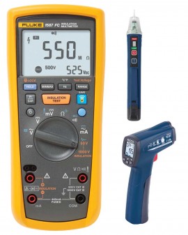
Ideal for troubleshooting and preventative maintenance, this insulation multimeter comes in a compact, handheld design, and features True RMS capabilities. This value added kit includes the REED R2300 Infrared Thermometer and the REED R5110 Non-Contact Voltage Detector for FREE.
Ideal for troubleshooting and preventative maintenance, this insulation multimeter comes in a compact, handheld design, and features True RMS capabilities. This value added kit includes the REED R2300 Infrared Thermometer and the REED R5110 Non-Contact Voltage Detector for FREE.
The high-performance 2-in-1 insulation digital multimeter
This insulation multimeter is the combination of a digital insulation tester that comes supplied with a full-featured, True RMS digital multimeter in a single compact, handheld unit, which enables maximum versatility for troubleshooting and preventative maintenance.
Features
Keep yourself safe. Find hidden problems faster. Put the paperwork down.
Fluke Connect and this insulation multimeter helps you identify tough problems, fix, and wirelessly communicate your work quickly and easily - all at a safe distance.
Add diagnostics with Fluke Connect
Fluke Connect is enabled so you can download the free application to your smartphone and gain additional functions, including:
REED R2300 Infrared Thermometer
This infrared thermometer features a 12:1 distance to spot ratio and is capable of measuring temperatures up to 752°F (400°C). The R2300 is an affordable non-contact measurement solution able to quickly and efficiently measure the temperature of hot, hazardous or hard-to reach objects from a safe distance.
Features
REED R5110 Non-Contact Voltage Detector with Flashlight
This Voltage Detector has the ability to detect the presence of AC voltage from a safe distance. The R5110 features two voltage ranges allowing it to detect both high (90 to 1000V) and low (24 to 1000V) AC voltage wiring.
Features
Disconnect any electronic devices like motor drives, PLC’s, transmitters, etc. before performing insulation testing. Electronics can be damaged by applying higher than normal voltage.
The effect of temperature should be considered - it is recommended that tests be performed at a standard conductor temperature of 20 °C (68 °F) or that a temperature baseline is established while compensating future readings by using a DMM with a probe or an infrared thermometer.
Select a test voltage appropriate for the insulation being tested. The objective is to stress the insulation but not to over-stress it. When in doubt, use a lower test voltage. It’s usually appropriate to test insulation at twice the voltage it normally sees: for example 460 V to 600 V rated equipment is often tested at 1000 V.
When using an insulation tester, leave the leads connected when you stop the test. The insulation tester can discharge any residual test voltage.
Conductors that are close to each other have a normal capacitance. This will cause an insulation resistance reading to start low and increase steadily until it stabilizes. This type of increase is normal, but if the reading jumps violently down and up again this indicates arcing.
Although the current is tightly limited, an insulation tester can generate sparks and minor but painful burns. The unexpected surprise can cause an operator to jerk away. As always, work away from live systems and use safe work practices when working overhead.
Infrared cameras, also called thermal imagers, are useful for troubleshooting motor problems as well as for monitoring motor condition for preventative maintenance in power generation, manufacturing and commercial plants. Thermal images of motors reveal their operating condition as indicated by surface temperature. Such condition monitoring is important as a way to avert many unexpected motor malfunctions in systems that are critical to manufacturing. The onset of motor failures can often be detected by a variety of techniques, including vibration, ultrasound and thermal imaging.
In this article, we cover why use thermal imaging and what to scan, as well as some notes on what to look for, including shaft misalignment.
Read the Article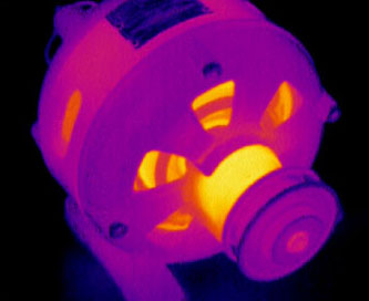
| AC Voltage Measurements | |
| Range | 600 mV 6 V 60 V 600 V 1000 V |
| Resolution | 0.1 mV 0.001 V 0.01 V 0.1 V 1 V |
| 50 to 60 Hz ±(% of Rdg + counts) | ±(1% + 3) ±(1% + 3) ±(1% + 3) ±(1% + 3) ±(2% + 3) |
| 60 to 5000 Hz ±(% of Rdg + counts) | ±(2% + 3) ±(2% + 3) ±(2% + 3) ±(2% + 3)1 ±(2% + 3)1 |
| Low-Pass Filter Voltage | |
| Range | 600 mV 6 V 60 V 600 V 1000 V |
| Resolution | 0.1 mV 0.001 V 0.01 V 0.1 V 1 V |
| 50 to 60 Hz ±(% of Rdg + counts) | ±(1% + 3) ±(1% + 3) ±(1% + 3) ±(1% + 3) ±(2% + 3) |
| 60 to 400 Hz ±(% of Rdg + counts) | ±(2% + 3) - (6% - 3) ±(2% + 3) - (6% - 3) ±(2% + 3) - (6% - 3) ±(2% + 3) - (6% - 3) ±(2% + 3) - (6% - 3) |
| DC Voltage Measurement | |
| Range | 6 V dc 60 V dc 600 V dc 1000 V dc |
| Resolution | 0.001 V 0.01 V 0.1 V 1 V |
| Accuracy ±(% of Rdg + Counts) | ±(0.09% + 2) ±(0.09% + 2) ±(0.09% + 2) ±(0.09% + 2) |
| Input Impedance | 10 MΩ (nominal), <100 pF |
| Nominal Mode Rejection Ratio | >60 dB at 50 or 60 Hz |
| Common Mode Rejection Ratio | >120 dB at dc, 50 or 60 Hz (1 k unbalance) |
| DC Millivolts Measurement | |
| Range | 600 mVdc |
| Resolution | 0.1 mV |
| Accuracy ±(% of Rdg + Counts) | ±(0.1 + 1) |
| DC and AC Current Measurement | |
| Range | 400 mA |
| Resolution | 0.1 mA |
| Accuracy ±(% of Rdg+Counts) | ±(1.5% + 2)1 |
| Burden Voltage (Typical) | 2 mV/mA |
| Range | 60 mA |
| Resolution | 0.01 mA |
| Accuracy ±(% of Rdg+Counts) | ±(1.5% + 2)1 |
| Burden Voltage (Typical) | 2 mV/mA |
| DC | |
| Range | 400 mA |
| Resolution | 0.1 mA |
| Accuracy ±(% of Rdg+Counts) | ±(0.2% + 2) |
| Burden Voltage (Typical) | 2 mV/mA |
| Range | 60 mA |
| Resolution | 0.01 mA |
| Accuracy ±(% of Rdg+Counts) | ±(0.2% + 2) |
| Burden Voltage (Typical) | 2 mV/mA |
| Overload | 600 mA for 2 minutes maximum |
| Fuse Protection for mA Input | 0.44 mA, 1000 V, IR 10 kA |
| AC Conversion | Inputs are ac-coupled and calibrated to the rms value of sine wave input |
| Ohms Measurement | |
| Range | 600 Ω 6 kΩ 60 kΩ 600 kΩ 6 MΩ 50 MΩ |
| Resolution | 0.1 Ω 0.001 kΩ 0.01 kΩ 0.1 kΩ 0.001 MΩ 0.01 MΩ |
| Accuracy +(% of Rdg+Counts)1 | ±(0.9% + 2) ±(0.9% + 2) ±(0.9% + 2) ±(0.9% + 2) ±(0.9% + 2) ±(1.5% + 3) |
| Overload Protection | 1000 rms or dc |
| Open Circuit Test Voltage | <8 V dc |
| Short Circuit Current | <1.1 mA |
| Diode Test | |
| Diode Test Indication | Display voltage drop: 0.6 V at1.0 mA nominal test current |
| Accuracy | ±(2% + 3) |
| Continuity Test | |
| Continuity Indication | Continuous audible tone for testresistance below 25 Ω and off above 100 Ω Maximum reading: 1000 Ω |
| Open Circuit Voltage | <8.0 V |
| Short Circuit Current | 1.0 mA typical |
| Overload Protection | 1000 V rms |
| Response Time | >1 m sec |
| Frequency Measurement | |
| Range | 99.99 Hz 999.9 Hz 9.999 kHz 99.99 kHz |
| Resolution | 0.01 Hz 0.1 Hz 0.001 kHz 0.01 kHz |
| Accuracy ±(% of Rdg+Counts) | ±(0.1% + 1) ±(0.1% + 1) ±(0.1% + 1) ±(0.1% + 1) |
| Frequency Counter Sensitivity | |
| 600.0 mV ac | V ac Sensitivity (RMS Sine Wave)1 5 Hz to 20 kHz: 100.0 mV V ac Sensitivity (RMS Sine Wave)1 20 to 100 kHz: 150.0 mV DC Trigger Levels¹ to 20 kHz2: NA |
| 6.0 V | V ac Sensitivity (RMS Sine Wave)1 5 Hz to 20 kHz: 1.0 V V ac Sensitivity (RMS Sine Wave)1 20 to 100 kHz: 1.5 V DC Trigger Levels¹ to 20 kHz2: -400.0 mV and 2.5 V |
| 60.0 V | V ac Sensitivity (RMS Sine Wave)1 5 Hz to 20 kHz: 10.0 V V ac Sensitivity (RMS Sine Wave)1 20 to 100 kHz: 36.0 V DC Trigger Levels¹ to 20 kHz2: 1.2 V and 4.0 V |
| 600.0 V | V ac Sensitivity (RMS Sine Wave)1 5 Hz to 20 kHz: 100.0 V V ac Sensitivity (RMS Sine Wave)1 20 to 100 kHz: NA DC Trigger Levels¹ to 20 kHz2: 12.0 V and 40.0 V |
| 1000.0 V | V ac Sensitivity (RMS Sine Wave)1 5 Hz to 20 kHz: 300.0 V V ac Sensitivity (RMS Sine Wave)1 20 to 100 kHz: NA DC Trigger Levels¹ to 20 kHz2: 12.0 V and 40.0 V |
| Capacitance | |
| Range | 1000 nF 10.00 µF 100.0 µF 9999 µF |
| Resolution | 1 nF 0.01 µF 0.1 µF 1 µF |
| Accuracy ±(% of Rdg+Counts) | ±(1.2% + 2) ±(1.2% + 2) ±(1.2% ± 90 counts) ±(1.2% ± 90 counts) |
| Temperature Measurement | |
| Range | -40 to 998°F (-40 to 537°C) |
| Resolution | 0.1°F (0.1°C) |
| Accuracy ±(% of Rdg+Counts)1 | ±(1% + 10 counts) ±(1% + 18 counts) |
| Insulation Specifications | |
| Measurement Range | 0.01 MΩ to 2 GΩ |
| Test Voltages | 50, 100, 250, 500, 1000 V |
| Test Voltage Accuracy | 20%, 0% |
| Short-Circuit Test Current | 1 mA nominal |
| Auto Discharge | Discharge time <0.5 second for C=1 µF or less |
| Live Circuit Detection | Inhibit test if terminal voltage >30 V prior to initialization of test |
| Maximum Capacitive Load | Operable with up to 1 µF load |
| Output Voltage | |
| 50 V (0% to +20%) | Display range: 0.01 to 6.00 MΩ Resolution: 0.01 MΩ Test current: 1 mA at 50 kΩ Resistance accuracy ±(% of Rdg + Counts): ±(3% + 5 counts) Display range: 6.0 to 50.0 MΩ Resolution: 0.1 MΩ Test current: 1 mA at 50 kΩ Resistance accuracy ±(% of Rdg + Counts): ±(3% + 5 counts) |
| 100 V (0% to +20%) | Display range: 0.01 to 6.00 MΩ Resolution: 0.01 MΩ Test current: 1 mA at 100 kΩ Resistance accuracy ±(% of Rdg + Counts): ±(3% + 5 counts) Display range: 6.0 to 60.0 MΩ Resolution: 0.1 MΩ Test current: 1 mA at 100 kΩ Resistance accuracy ±(% of Rdg + Counts): ±(3% + 5 counts) Display range: 6.0 to 100.0 MΩ Resolution: 0.1 MΩ Test current: 1 mA at 100 kΩ Resistance accuracy ±(% of Rdg + Counts): ±(3% + 5 counts) |
| 250 V (0% to +20%) | Display range: 0.1 to 60.0 MΩ Resolution: 0.1 MΩ Test current: 1 mA at 250 kΩ Resistance accuracy ±(% of Rdg + Counts): ±(1.5% + 5 counts) Display range: 60 to 250 MΩ Resolution: 1 MΩ Test current: 1 mA at 250 kΩ Resistance accuracy ±(% of Rdg + Counts): ±(1.5% + 5 counts) |
| 500 V (0% to +20%) | Display range: 0.1 to 60.0 MΩ Resolution: 0.1 MΩ Test current: 1 mA at 500 kΩ Resistance accuracy ±(% of Rdg + Counts): ±(1.5% + 5 counts) Display range: 60 to 500 MΩ Resolution: 1 MΩ Test current: 1 mA at 250 kΩ Resistance accuracy ±(% of Rdg + Counts): ±(1.5% + 5 counts) |
| 1000 V (0% to +20%) | Display range: 0.1 to 60.0 MΩ Resolution: 0.1 MΩ Test current: 1 mA at 1 MΩ Resistance accuracy ±(% of Rdg + Counts): ±(1.5% + 5 counts) Display range: 60 to 600 MΩ Resolution: 1 MΩ Test current: 1 mA at 1 MΩ Resistance accuracy ±(% of Rdg + Counts): ±(1.5% + 5 counts) Display range: 0.6 to 2.0 GΩ Resolution: 100 MΩ Test current: 1 mA at 1 MΩ Resistance accuracy ±(% of Rdg + Counts): ±(10% + 3 counts) |

Perform insulation tests with voltages 50V, 100V, 250V, 500V, 1000V. Capable of testing frequency, capacitance, temperature, AC/DC voltage and more. Part of the Fluke Connect family of wireless test tools.

Fast responding entry-level infrared thermometer with min/max temperature readings and adjustable high/low temperature alarms.

AC Voltage Detector with built-in flashlight and pocket clip.
 |
 |
 |
 |
 |
 |
|
|---|---|---|---|---|---|---|
| Two in one tools | Stand-alone tools | |||||
| Insulation test features | 1587 FC | 1577 | 1503 | 1507 | 1550C | 1555 |
| Test voltages | 50 V, 100 V, 250 V, 500 V, 1000 V | 500 V, 1000 V | 500 V, 1000 V | 50 V, 100 V, 250 V, 500 V, 1000 V | 250 V to 5000 V | 250 V to 10,000 V |
| Insulation resistance range | 0.01 MΩ to 2 GΩ | 0.01 MΩ to 600 GΩ | 0.01 MΩ to 2000 GΩ | 0.01 MΩ to 10 GΩ | 250 kΩ to 1 TΩ | 250 kΩ to 2 TΩ |
| PI/DAR | ||||||
| Auto discharge | ||||||
| Timed ramp test (Breakdown) | ||||||
| Pass/fail comparison | ||||||
| Est. # of IRT tests | 1000 | 1000 | 2000 | 2000 | Various | Various |
| Voltage > 30 V warning | ||||||
| Memory | With Fluke Connect App | |||||
| Remote test probe | ||||||
| Lo ohms/earth-bond continuity | 200 mA source (10 mΩ resolution) | 200 mA source (10 mΩ resolution) | ||||
| Display | Digital LCD | Digital LCD | Digital LCD | Digital LCD | Digital LCD/ analog display | Digital LCD/ analog display |
| Hold/lock | ||||||
| Multimeter features | ||||||
| AC/DC volts | Note: Not all product features and specifications are listed in this table. For more complete information, see individual product data sheets. Footnotes: |
|||||
| Current | ||||||
| Resistance | ||||||
| Continuity beeper | ||||||
| Temperature (contact) | ||||||
| Lo-pass filter2 | ||||||
| Capacitance | ||||||
| Diode test | ||||||
| Frequency | ||||||
| MIN/MAX | ||||||
| Other features | ||||||
| Backlight | ||||||
| Software | Fluke Connect compatible | FlukeView® Forms Basic | Fluke View® Forms Basic | |||
| Battery | 4 AA (NEDA 15A or IEC LR6) | 4 AA (NEDA 15A or IEC LR6) | 4 AA (NEDA 15A or IEC LR6) | 4 AA (NEDA 15A or IEC LR6) | Rechargeable | Rechargeable |

Fluke engineers have delivered an innovative mobile platform and tool that helps solve everyday problems, allowing you to instantly document measurements, retrieve historical data, and share live measurements with your team. All handled by the Android™ or iOS smart phone you already carry.
Fluke Connect with ShareLive™ video call is the only wireless measurement system that lets you stay in contact with your entire team without leaving the field. The Fluke Connect mobile app is works with over 20 different Fluke products - the largest suite of connected test tools in the world.
Make the best decisions faster than ever before by viewing temperature, mechanical, electrical and vibration measurements for each equipment asset in one place. Get started saving time and increasing your productivity.
 In the past, motor repair meant dealing with traditional three-phase motor failures that were largely the result of water, dust, grease, failed bearings, misaligned motor shafts, or just plain old age. But motor repair has changed in a big way with the introduction of electronically controlled motors, more commonly referred to as adjustable speed drives (ASDs). These drives present a unique set of measurement problems that can vex the most seasoned pro. Thanks to new technology, now for the first time you can take accurate electrical measurements with a DMM during the installation and maintenance of a drive and diagnose bad components and other conditions that may lead to premature failure.

Technicians use many different methods to troubleshoot an electrical circuit, and a good troubleshooter will always find the problem - eventually. The trick is tracking it down quickly and keeping downtime to a minimum. The most efficient troubleshooting procedure begins at the motor and then works systematically back to the electrical source, looking for the most obvious problems first. A lot of time and money can be wasted replacing perfectly good parts when the problem is simply a loose connection. As you go, take care to take accurate measurements. Nobody takes inaccurate measurements on purpose, but it's easy to do, especially when working in a high-energy, noisy environment like an ASD. Likewise, choosing the right test tools for troubleshooting the drive, the motor, and the connections are of utmost importance. This is especially true when taking voltage, frequency, and current measurements on the output side of the motor drive. But until now, there hasn't been a digital multimeter on the market able to accurately measure ASDs. Incorporates a selectable low pass filter* that allows for accurate drive output measurements that agree with the motor drive controller display indicator. Now, technicians won't have to guess whether the drive is operating correctly and delivering the correct voltage, current, or frequency for a given control setting.
Input side measurements
Any good quality True RMS multimeter can verify proper input power to an ASD. The input voltage readings should be within 1% of one another when measured from phase to phase with no load. A significant unbalance may lead to erratic drive operation and should be corrected when discovered.

Output side measurements
On the flip side, a regular True RMS multimeter can't reliably read the output side of a pulse width modulated (PWM) motor drive, because the ASD applies pulse width modulated nonsinusoidal voltage to the motor terminals. A True RMS DMM reads the heating effect of the non-sinusoidal voltage applied to the motor, while the motor controller's output voltage reading only displays the RMS value of the fundamental component (typically from 30 Hz to 60 Hz). The causes of this discrepancy are bandwidth and shielding. Many of today's True RMS digital multimeters have bandwidths out to 20 kHz or more, causing them to respond not only to the fundamental component, which is what the motor responds to but to all of the high-frequency components generated by the PWM drive. And if the DMM isn't shielded for high-frequency noise, the drive controller's high noise levels make the measurement discrepancies even more extreme. With the bandwidth and shielding issues combined, many True RMS meters display readings as much as 20 to 30% higher than what the drive controller is indicating. The incorporated selectable low pass filter allows troubleshooters to take accurate voltage, current, and frequency measurements on the output side of the drive at either the drive itself or the motor terminals. With the filter selected, the readings for both voltage and frequency (motor speed) should agree with the associated drive control display indications, if available. The low pass filter also allows for accurate current measurements when used with Hall-effect type clamps. All of these measurements are especially helpful when taking measurements at the motor location when the drive's displays are not in view.
Taking safe measurements
Before taking any electrical measurements, be sure you understand how to take them safely. No test instrument is completely safe if used improperly, and many test instruments are not appropriate for testing adjustable speed drives. Also, make sure to use the appropriate personal protective equipment (PPE) for your specific working environment and measurements. If at all possible, never work alone.


Safety ratings for electrical test equipment
ANSI and the International Electrotechnical Commission (IEC) are the primary independent organizations that define safety standards for test equipment manufacturers. The IEC 61010 second edition standard for test equipment safety states two basic parameters: a voltage rating and a measurement category rating. The voltage rating is the maximum continuous working voltage the instrument is capable of measuring. The category ratings depict the measurement environment expected for a given category. Most three-phase ASD installations would be considered a CAT III measurement environment, with power supplied from either 480V or 600V distribution systems. When using a DMM for measurements on these high-energy systems, make sure it's rated at a minimum for CAT III 600V and preferably for CAT IV 600V/CAT III 1000V. The category rating and voltage limit are typically found on the front panel, at the input terminals. Dual-rated CAT IV 600V and CAT III 1000V. Refer to the ABC's of DMM Safety* from Fluke for additional information on category ratings and taking safe measurements.
Now let's put the multimeter to the test. The measurements in the following procedure are designed to be made on a 480 volt 3 phase drive control at the control panel terminal strips. These procedures would also be valid for lower voltage 3 phase drives powered by either single or 3 phase supply voltages. For these tests, the motor is running at 50 Hz.
Input voltage
To measure the ac voltage supply to the input side of the drive at the drive:
Input current
Measuring the input current generally requires a current clamp accessory. In most cases, either the input current exceeds the maximum current measurable by the current function, or it isn't practical to "break the circuit" to take an in-line series current measurement. Regardless of clamp type, insure that all readings are within 10% of each other for proper balance.
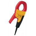
Transformer type clamp (i200, 80i-400, 80i-600A)
Hall Effect type (AC/DC) clamp (i410,i-1010)
Figure 1. Output voltage reading without using the low pass filter.


Figure 2. Output voltage reading with low pass filter enabled.

Output voltage
To measure the AC output voltage at either the drive or the motor terminals:
Figure 3. Output frequency (motor speed) without the low pass filter.
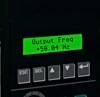

Figure 4. Output frequency (motor speed) using the low pass filter.

Motor speed (Output frequency using voltage as a reference)
To determine motor speed, simply take a frequency measurement while using the low pass filter. The measurement can be made between any two of the phase voltage or motor terminals.
Output current
TAs with input current, measuring the output current generally requires a current clamp accessory. Once again, regardless of clamp type, insure that all readings are within 10% of each other for proper balance.
Transformer type clamp (i200, 80i-400, 80i-600A)
Figure 5. Output current reading without using the low pass filter.


Figure 6. Output current reading with low pass filter enabled.

Hall Effect type (AC/DC) clamp (i410,i-1010)
Motor speed (Output frequency using current as a reference)
For motors that pull at least 20 amps of running current, motor speed can be determined by taking a frequency measurement with current clamps. Until now, noise issues have prevented accurate readings using hall effect type clamps. Here's how the low pass filter makes it possible.
Motor speed using a Hall Effect type (AC/DC) clamp (i410,i-1010)
Motor speed using a transformer type clamp (i200, 80i-400, 80i-600A)
DC Bus measurements
A healthy dc bus is a must for a properly operating motor drive. If the bus voltage is incorrect or unstable, the converter diodes or capacitors may be starting to fail. The DC bus voltage should be approximately 1.414 times the phase to phase input voltage. For a 480 volt input, the DC bus should be approximately 679 VDC. The DC bus is typically labeled as DC+, DC- or B+, Bon the drive terminal strip. To measure the DC bus voltage:
Click on a category to view a selection of compatible accessories with the Fluke 1587FC Insulation Multimeter Kit - Includes FREE Products with Purchase.


| AC Voltage Measurements | |
| Range | 600 mV 6 V 60 V 600 V 1000 V |
| Resolution | 0.1 mV 0.001 V 0.01 V 0.1 V 1 V |
| 50 to 60 Hz ±(% of Rdg + counts) | ±(1% + 3) ±(1% + 3) ±(1% + 3) ±(1% + 3) ±(2% + 3) |
| 60 to 5000 Hz ±(% of Rdg + counts) | ±(2% + 3) ±(2% + 3) ±(2% + 3) ±(2% + 3)1 ±(2% + 3)1 |
| Low-Pass Filter Voltage | |
| Range | 600 mV 6 V 60 V 600 V 1000 V |
| Resolution | 0.1 mV 0.001 V 0.01 V 0.1 V 1 V |
| 50 to 60 Hz ±(% of Rdg + counts) | ±(1% + 3) ±(1% + 3) ±(1% + 3) ±(1% + 3) ±(2% + 3) |
| 60 to 400 Hz ±(% of Rdg + counts) | ±(2% + 3) - (6% - 3) ±(2% + 3) - (6% - 3) ±(2% + 3) - (6% - 3) ±(2% + 3) - (6% - 3) ±(2% + 3) - (6% - 3) |
| DC Voltage Measurement | |
| Range | 6 V dc 60 V dc 600 V dc 1000 V dc |
| Resolution | 0.001 V 0.01 V 0.1 V 1 V |
| Accuracy ±(% of Rdg + Counts) | ±(0.09% + 2) ±(0.09% + 2) ±(0.09% + 2) ±(0.09% + 2) |
| Input Impedance | 10 MΩ (nominal), <100 pF |
| Nominal Mode Rejection Ratio | >60 dB at 50 or 60 Hz |
| Common Mode Rejection Ratio | >120 dB at dc, 50 or 60 Hz (1 k unbalance) |
| DC Millivolts Measurement | |
| Range | 600 mVdc |
| Resolution | 0.1 mV |
| Accuracy ±(% of Rdg + Counts) | ±(0.1 + 1) |
| DC and AC Current Measurement | |
| Range | 400 mA |
| Resolution | 0.1 mA |
| Accuracy ±(% of Rdg+Counts) | ±(1.5% + 2)1 |
| Burden Voltage (Typical) | 2 mV/mA |
| Range | 60 mA |
| Resolution | 0.01 mA |
| Accuracy ±(% of Rdg+Counts) | ±(1.5% + 2)1 |
| Burden Voltage (Typical) | 2 mV/mA |
| DC | |
| Range | 400 mA |
| Resolution | 0.1 mA |
| Accuracy ±(% of Rdg+Counts) | ±(0.2% + 2) |
| Burden Voltage (Typical) | 2 mV/mA |
| Range | 60 mA |
| Resolution | 0.01 mA |
| Accuracy ±(% of Rdg+Counts) | ±(0.2% + 2) |
| Burden Voltage (Typical) | 2 mV/mA |
| Overload | 600 mA for 2 minutes maximum |
| Fuse Protection for mA Input | 0.44 mA, 1000 V, IR 10 kA |
| AC Conversion | Inputs are ac-coupled and calibrated to the rms value of sine wave input |
| Ohms Measurement | |
| Range | 600 Ω 6 kΩ 60 kΩ 600 kΩ 6 MΩ 50 MΩ |
| Resolution | 0.1 Ω 0.001 kΩ 0.01 kΩ 0.1 kΩ 0.001 MΩ 0.01 MΩ |
| Accuracy +(% of Rdg+Counts)1 | ±(0.9% + 2) ±(0.9% + 2) ±(0.9% + 2) ±(0.9% + 2) ±(0.9% + 2) ±(1.5% + 3) |
| Overload Protection | 1000 rms or dc |
| Open Circuit Test Voltage | <8 V dc |
| Short Circuit Current | <1.1 mA |
| Diode Test | |
| Diode Test Indication | Display voltage drop: 0.6 V at1.0 mA nominal test current |
| Accuracy | ±(2% + 3) |
| Continuity Test | |
| Continuity Indication | Continuous audible tone for testresistance below 25 Ω and off above 100 Ω Maximum reading: 1000 Ω |
| Open Circuit Voltage | <8.0 V |
| Short Circuit Current | 1.0 mA typical |
| Overload Protection | 1000 V rms |
| Response Time | >1 m sec |
| Frequency Measurement | |
| Range | 99.99 Hz 999.9 Hz 9.999 kHz 99.99 kHz |
| Resolution | 0.01 Hz 0.1 Hz 0.001 kHz 0.01 kHz |
| Accuracy ±(% of Rdg+Counts) | ±(0.1% + 1) ±(0.1% + 1) ±(0.1% + 1) ±(0.1% + 1) |
| Frequency Counter Sensitivity | |
| 600.0 mV ac | V ac Sensitivity (RMS Sine Wave)1 5 Hz to 20 kHz: 100.0 mV V ac Sensitivity (RMS Sine Wave)1 20 to 100 kHz: 150.0 mV DC Trigger Levels¹ to 20 kHz2: NA |
| 6.0 V | V ac Sensitivity (RMS Sine Wave)1 5 Hz to 20 kHz: 1.0 V V ac Sensitivity (RMS Sine Wave)1 20 to 100 kHz: 1.5 V DC Trigger Levels¹ to 20 kHz2: -400.0 mV and 2.5 V |
| 60.0 V | V ac Sensitivity (RMS Sine Wave)1 5 Hz to 20 kHz: 10.0 V V ac Sensitivity (RMS Sine Wave)1 20 to 100 kHz: 36.0 V DC Trigger Levels¹ to 20 kHz2: 1.2 V and 4.0 V |
| 600.0 V | V ac Sensitivity (RMS Sine Wave)1 5 Hz to 20 kHz: 100.0 V V ac Sensitivity (RMS Sine Wave)1 20 to 100 kHz: NA DC Trigger Levels¹ to 20 kHz2: 12.0 V and 40.0 V |
| 1000.0 V | V ac Sensitivity (RMS Sine Wave)1 5 Hz to 20 kHz: 300.0 V V ac Sensitivity (RMS Sine Wave)1 20 to 100 kHz: NA DC Trigger Levels¹ to 20 kHz2: 12.0 V and 40.0 V |
| Capacitance | |
| Range | 1000 nF 10.00 µF 100.0 µF 9999 µF |
| Resolution | 1 nF 0.01 µF 0.1 µF 1 µF |
| Accuracy ±(% of Rdg+Counts) | ±(1.2% + 2) ±(1.2% + 2) ±(1.2% ± 90 counts) ±(1.2% ± 90 counts) |
| Temperature Measurement | |
| Range | -40 to 998°F (-40 to 537°C) |
| Resolution | 0.1°F (0.1°C) |
| Accuracy ±(% of Rdg+Counts)1 | ±(1% + 10 counts) ±(1% + 18 counts) |
| Insulation Specifications | |
| Measurement Range | 0.01 MΩ to 2 GΩ |
| Test Voltages | 50, 100, 250, 500, 1000 V |
| Test Voltage Accuracy | 20%, 0% |
| Short-Circuit Test Current | 1 mA nominal |
| Auto Discharge | Discharge time <0.5 second for C=1 µF or less |
| Live Circuit Detection | Inhibit test if terminal voltage >30 V prior to initialization of test |
| Maximum Capacitive Load | Operable with up to 1 µF load |
| Output Voltage | |
| 50 V (0% to +20%) | Display range: 0.01 to 6.00 MΩ Resolution: 0.01 MΩ Test current: 1 mA at 50 kΩ Resistance accuracy ±(% of Rdg + Counts): ±(3% + 5 counts) Display range: 6.0 to 50.0 MΩ Resolution: 0.1 MΩ Test current: 1 mA at 50 kΩ Resistance accuracy ±(% of Rdg + Counts): ±(3% + 5 counts) |
| 100 V (0% to +20%) | Display range: 0.01 to 6.00 MΩ Resolution: 0.01 MΩ Test current: 1 mA at 100 kΩ Resistance accuracy ±(% of Rdg + Counts): ±(3% + 5 counts) Display range: 6.0 to 60.0 MΩ Resolution: 0.1 MΩ Test current: 1 mA at 100 kΩ Resistance accuracy ±(% of Rdg + Counts): ±(3% + 5 counts) Display range: 6.0 to 100.0 MΩ Resolution: 0.1 MΩ Test current: 1 mA at 100 kΩ Resistance accuracy ±(% of Rdg + Counts): ±(3% + 5 counts) |
| 250 V (0% to +20%) | Display range: 0.1 to 60.0 MΩ Resolution: 0.1 MΩ Test current: 1 mA at 250 kΩ Resistance accuracy ±(% of Rdg + Counts): ±(1.5% + 5 counts) Display range: 60 to 250 MΩ Resolution: 1 MΩ Test current: 1 mA at 250 kΩ Resistance accuracy ±(% of Rdg + Counts): ±(1.5% + 5 counts) |
| 500 V (0% to +20%) | Display range: 0.1 to 60.0 MΩ Resolution: 0.1 MΩ Test current: 1 mA at 500 kΩ Resistance accuracy ±(% of Rdg + Counts): ±(1.5% + 5 counts) Display range: 60 to 500 MΩ Resolution: 1 MΩ Test current: 1 mA at 250 kΩ Resistance accuracy ±(% of Rdg + Counts): ±(1.5% + 5 counts) |
| 1000 V (0% to +20%) | Display range: 0.1 to 60.0 MΩ Resolution: 0.1 MΩ Test current: 1 mA at 1 MΩ Resistance accuracy ±(% of Rdg + Counts): ±(1.5% + 5 counts) Display range: 60 to 600 MΩ Resolution: 1 MΩ Test current: 1 mA at 1 MΩ Resistance accuracy ±(% of Rdg + Counts): ±(1.5% + 5 counts) Display range: 0.6 to 2.0 GΩ Resolution: 100 MΩ Test current: 1 mA at 1 MΩ Resistance accuracy ±(% of Rdg + Counts): ±(10% + 3 counts) |
Perform insulation tests with voltages 50V, 100V, 250V, 500V, 1000V. Capable of testing frequency, capacitance, temperature, AC/DC voltage and more. Part of the Fluke Connect family of wireless test tools.
Fast responding entry-level infrared thermometer with min/max temperature readings and adjustable high/low temperature alarms.
AC Voltage Detector with built-in flashlight and pocket clip.
|
|
|
|
|
|
|
|---|---|---|---|---|---|---|
| Two in one tools | Stand-alone tools | |||||
| Insulation test features | 1587 FC | 1577 | 1503 | 1507 | 1550C | 1555 |
| Test voltages | 50 V, 100 V, 250 V, 500 V, 1000 V | 500 V, 1000 V | 500 V, 1000 V | 50 V, 100 V, 250 V, 500 V, 1000 V | 250 V to 5000 V | 250 V to 10,000 V |
| Insulation resistance range | 0.01 MΩ to 2 GΩ | 0.01 MΩ to 600 GΩ | 0.01 MΩ to 2000 GΩ | 0.01 MΩ to 10 GΩ | 250 kΩ to 1 TΩ | 250 kΩ to 2 TΩ |
| PI/DAR | ||||||
| Auto discharge | ||||||
| Timed ramp test (Breakdown) | ||||||
| Pass/fail comparison | ||||||
| Est. # of IRT tests | 1000 | 1000 | 2000 | 2000 | Various | Various |
| Voltage > 30 V warning | ||||||
| Memory | With Fluke Connect App | |||||
| Remote test probe | ||||||
| Lo ohms/earth-bond continuity | 200 mA source (10 mΩ resolution) | 200 mA source (10 mΩ resolution) | ||||
| Display | Digital LCD | Digital LCD | Digital LCD | Digital LCD | Digital LCD/ analog display | Digital LCD/ analog display |
| Hold/lock | ||||||
| Multimeter features | ||||||
| AC/DC volts | Note: Not all product features and specifications are listed in this table. For more complete information, see individual product data sheets. Footnotes: |
|||||
| Current | ||||||
| Resistance | ||||||
| Continuity beeper | ||||||
| Temperature (contact) | ||||||
| Lo-pass filter2 | ||||||
| Capacitance | ||||||
| Diode test | ||||||
| Frequency | ||||||
| MIN/MAX | ||||||
| Other features | ||||||
| Backlight | ||||||
| Software | Fluke Connect compatible | FlukeView® Forms Basic | Fluke View® Forms Basic | |||
| Battery | 4 AA (NEDA 15A or IEC LR6) | 4 AA (NEDA 15A or IEC LR6) | 4 AA (NEDA 15A or IEC LR6) | 4 AA (NEDA 15A or IEC LR6) | Rechargeable | Rechargeable |
Fluke engineers have delivered an innovative mobile platform and tool that helps solve everyday problems, allowing you to instantly document measurements, retrieve historical data, and share live measurements with your team. All handled by the Android™ or iOS smart phone you already carry.
Fluke Connect with ShareLive™ video call is the only wireless measurement system that lets you stay in contact with your entire team without leaving the field. The Fluke Connect mobile app is works with over 20 different Fluke products - the largest suite of connected test tools in the world.
Make the best decisions faster than ever before by viewing temperature, mechanical, electrical and vibration measurements for each equipment asset in one place. Get started saving time and increasing your productivity.
In the past, motor repair meant dealing with traditional three-phase motor failures that were largely the result of water, dust, grease, failed bearings, misaligned motor shafts, or just plain old age. But motor repair has changed in a big way with the introduction of electronically controlled motors, more commonly referred to as adjustable speed drives (ASDs). These drives present a unique set of measurement problems that can vex the most seasoned pro. Thanks to new technology, now for the first time you can take accurate electrical measurements with a DMM during the installation and maintenance of a drive and diagnose bad components and other conditions that may lead to premature failure.
Technicians use many different methods to troubleshoot an electrical circuit, and a good troubleshooter will always find the problem - eventually. The trick is tracking it down quickly and keeping downtime to a minimum. The most efficient troubleshooting procedure begins at the motor and then works systematically back to the electrical source, looking for the most obvious problems first. A lot of time and money can be wasted replacing perfectly good parts when the problem is simply a loose connection. As you go, take care to take accurate measurements. Nobody takes inaccurate measurements on purpose, but it's easy to do, especially when working in a high-energy, noisy environment like an ASD. Likewise, choosing the right test tools for troubleshooting the drive, the motor, and the connections are of utmost importance. This is especially true when taking voltage, frequency, and current measurements on the output side of the motor drive. But until now, there hasn't been a digital multimeter on the market able to accurately measure ASDs. Incorporates a selectable low pass filter* that allows for accurate drive output measurements that agree with the motor drive controller display indicator. Now, technicians won't have to guess whether the drive is operating correctly and delivering the correct voltage, current, or frequency for a given control setting.
Input side measurements
Any good quality True RMS multimeter can verify proper input power to an ASD. The input voltage readings should be within 1% of one another when measured from phase to phase with no load. A significant unbalance may lead to erratic drive operation and should be corrected when discovered.
Output side measurements
On the flip side, a regular True RMS multimeter can't reliably read the output side of a pulse width modulated (PWM) motor drive, because the ASD applies pulse width modulated nonsinusoidal voltage to the motor terminals. A True RMS DMM reads the heating effect of the non-sinusoidal voltage applied to the motor, while the motor controller's output voltage reading only displays the RMS value of the fundamental component (typically from 30 Hz to 60 Hz). The causes of this discrepancy are bandwidth and shielding. Many of today's True RMS digital multimeters have bandwidths out to 20 kHz or more, causing them to respond not only to the fundamental component, which is what the motor responds to but to all of the high-frequency components generated by the PWM drive. And if the DMM isn't shielded for high-frequency noise, the drive controller's high noise levels make the measurement discrepancies even more extreme. With the bandwidth and shielding issues combined, many True RMS meters display readings as much as 20 to 30% higher than what the drive controller is indicating. The incorporated selectable low pass filter allows troubleshooters to take accurate voltage, current, and frequency measurements on the output side of the drive at either the drive itself or the motor terminals. With the filter selected, the readings for both voltage and frequency (motor speed) should agree with the associated drive control display indications, if available. The low pass filter also allows for accurate current measurements when used with Hall-effect type clamps. All of these measurements are especially helpful when taking measurements at the motor location when the drive's displays are not in view.
Taking safe measurements
Before taking any electrical measurements, be sure you understand how to take them safely. No test instrument is completely safe if used improperly, and many test instruments are not appropriate for testing adjustable speed drives. Also, make sure to use the appropriate personal protective equipment (PPE) for your specific working environment and measurements. If at all possible, never work alone.
Safety ratings for electrical test equipment
ANSI and the International Electrotechnical Commission (IEC) are the primary independent organizations that define safety standards for test equipment manufacturers. The IEC 61010 second edition standard for test equipment safety states two basic parameters: a voltage rating and a measurement category rating. The voltage rating is the maximum continuous working voltage the instrument is capable of measuring. The category ratings depict the measurement environment expected for a given category. Most three-phase ASD installations would be considered a CAT III measurement environment, with power supplied from either 480V or 600V distribution systems. When using a DMM for measurements on these high-energy systems, make sure it's rated at a minimum for CAT III 600V and preferably for CAT IV 600V/CAT III 1000V. The category rating and voltage limit are typically found on the front panel, at the input terminals. Dual-rated CAT IV 600V and CAT III 1000V. Refer to the ABC's of DMM Safety* from Fluke for additional information on category ratings and taking safe measurements.
Now let's put the multimeter to the test. The measurements in the following procedure are designed to be made on a 480 volt 3 phase drive control at the control panel terminal strips. These procedures would also be valid for lower voltage 3 phase drives powered by either single or 3 phase supply voltages. For these tests, the motor is running at 50 Hz.
Input voltage
To measure the ac voltage supply to the input side of the drive at the drive:
Input current
Measuring the input current generally requires a current clamp accessory. In most cases, either the input current exceeds the maximum current measurable by the current function, or it isn't practical to "break the circuit" to take an in-line series current measurement. Regardless of clamp type, insure that all readings are within 10% of each other for proper balance.
Transformer type clamp (i200, 80i-400, 80i-600A)
Hall Effect type (AC/DC) clamp (i410,i-1010)
Figure 1. Output voltage reading without using the low pass filter.
Figure 2. Output voltage reading with low pass filter enabled.
Output voltage
To measure the AC output voltage at either the drive or the motor terminals:
Figure 3. Output frequency (motor speed) without the low pass filter.
Figure 4. Output frequency (motor speed) using the low pass filter.
Motor speed (Output frequency using voltage as a reference)
To determine motor speed, simply take a frequency measurement while using the low pass filter. The measurement can be made between any two of the phase voltage or motor terminals.
Output current
TAs with input current, measuring the output current generally requires a current clamp accessory. Once again, regardless of clamp type, insure that all readings are within 10% of each other for proper balance.
Transformer type clamp (i200, 80i-400, 80i-600A)
Figure 5. Output current reading without using the low pass filter.
Figure 6. Output current reading with low pass filter enabled.
Hall Effect type (AC/DC) clamp (i410,i-1010)
Motor speed (Output frequency using current as a reference)
For motors that pull at least 20 amps of running current, motor speed can be determined by taking a frequency measurement with current clamps. Until now, noise issues have prevented accurate readings using hall effect type clamps. Here's how the low pass filter makes it possible.
Motor speed using a Hall Effect type (AC/DC) clamp (i410,i-1010)
Motor speed using a transformer type clamp (i200, 80i-400, 80i-600A)
DC Bus measurements
A healthy dc bus is a must for a properly operating motor drive. If the bus voltage is incorrect or unstable, the converter diodes or capacitors may be starting to fail. The DC bus voltage should be approximately 1.414 times the phase to phase input voltage. For a 480 volt input, the DC bus should be approximately 679 VDC. The DC bus is typically labeled as DC+, DC- or B+, Bon the drive terminal strip. To measure the DC bus voltage:
Click on a category to view a selection of compatible accessories with the Fluke 1587FC Insulation Multimeter Kit - Includes FREE Products with Purchase.